Overview
Transforming a design CAD model into a geometry that is appropriate for simulation requires a different focus than CAD systems generally provide. The ability to quickly identify and remove unneeded features in the model is a very important capability. Augmentation of the model to support ease of mesh generation as well as specification of analysis attributes (boundary conditions etc.) for the simulation is also critical. Support for both mixed dimension models and non-manifold geometry (often not well supported in CAD sytems) is also needed. SimModeler provides all of these capabilites in an easy to use application.
In addition to working with CAD geometry, SimModeler is also designed to work with discrete geometry (mesh-based geometry from STL or other sources). Tools are available to detect issues with the mesh and perform local and global improvement and repair operations. Full boolean capabilities are available to union individual parts.
Capabilities:
- Simplify models for simulation. Remove parts from assemblies, model entities from parts, simplify surfaces
- Add far field regions for flow analysis
- Modify model geometry (add model edges/faces) for meshing or solver analysis application
- Fix assembly misalignments
Model Simplification: Automatic Feature Detection and Removal
Often the geometric model may have more details than what are needed for the desired simulation. Through automatic detection of features, and interactive selection, the model can quickly be simplified.
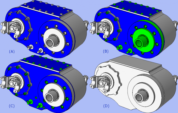
(A) A few key faces for auto-detection are selected in blue.
(B) Auto-detection returns sets of connected model faces, either between the key faces or within a given key face.
(C) Since the auto-detected faces are returned in sets, it is easy to de-select groups that should remain.
(D) The rest of the features are then removed with one click, and the model is now ready for simulation.
Model Courtesy Randall E.
Model Modification
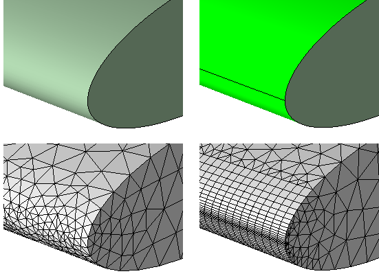
By splitting the leading edge of the airfoil wing, advanced meshing attributes (in this case 2D boundary layers) can be added.
On left, the original model face and subsequent mesh. On right, the model face as it is being split and the resultant mesh using 2D boundary layers.
Model Simplification:
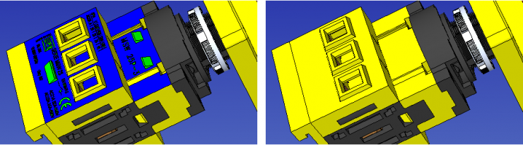
Part Removal
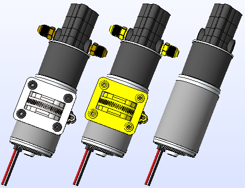
Sometimes the model provided contains extra parts in the assembly which aren't needed for analysis. In the above pump model, the mounting hardware is extraneous, and can be removed.
Model Courtesy Nathan Brooks
Model Adjustments
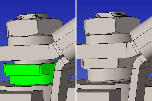
It might be necessary in some cases to re-align parts in an assembly. Above, a bolt part is repositioned higher in the assembly structure.
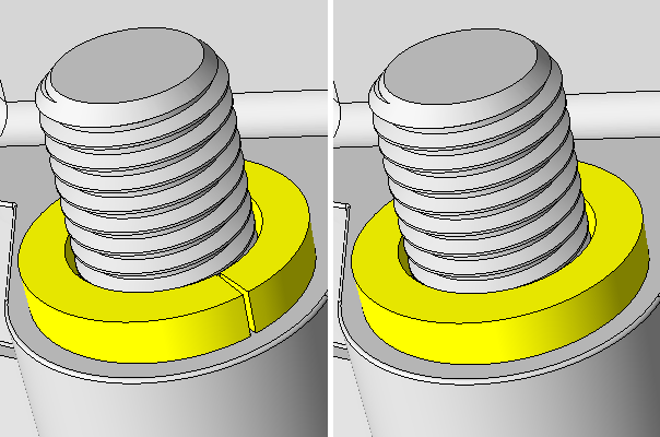
Below, a split washer is converted to a whole washer by offsetting the split face.