

Extrusion Meshing
Overview
Extrusion meshing generates a structured mesh along the extrusion direction on the given model entity. It can be combined with other meshing capabilities, such as boundary layers and mesh matching.
Capabilities:
- 2D Face extrusions and 3D Region extrusion
- Extruded boundary layers
- Multiple source faces to single destination face volume extrusions
- Complete control over layer height distribution
- Tetrahedral, wedge, or hexahedral extrusion elements
- Radial extrusions
- Automatic resolution of source/destination faces for chained extrusions
- Closed-loop extrusions
Embedded Volume Boundary Layers
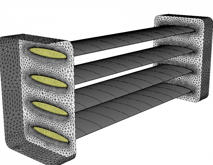
The fins of this model are individual regions that are extruded. There are boundary layers specified to capture flow through the fins. These boundary layers transition from the unstructured mesh seamlessly to the extruded mesh.
Curved Path Extrusions
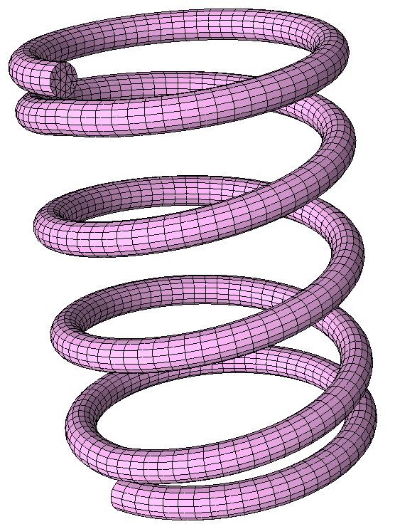
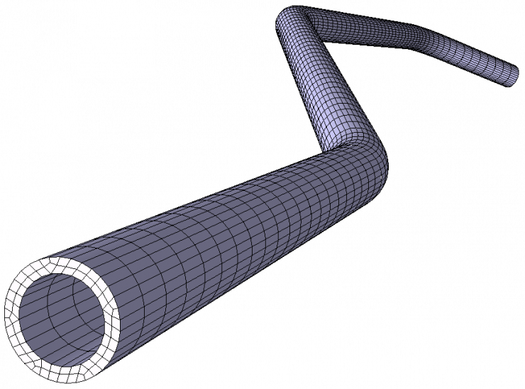
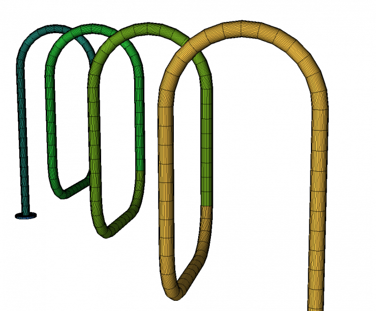
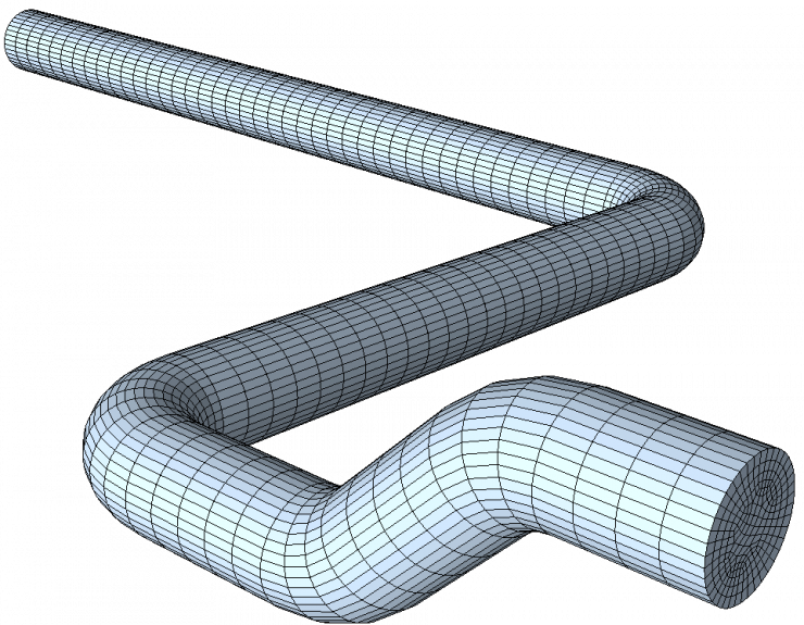
Various examples of extrusion along a curved path
Automatic resolution of extrusion directions
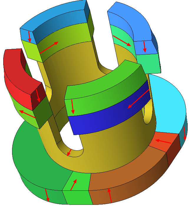
Extrusions may be specified in multiple directions as show by the red arrows. These will be automatically resolved to handle which extrusion should be performed when and in which direction.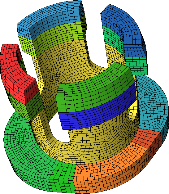
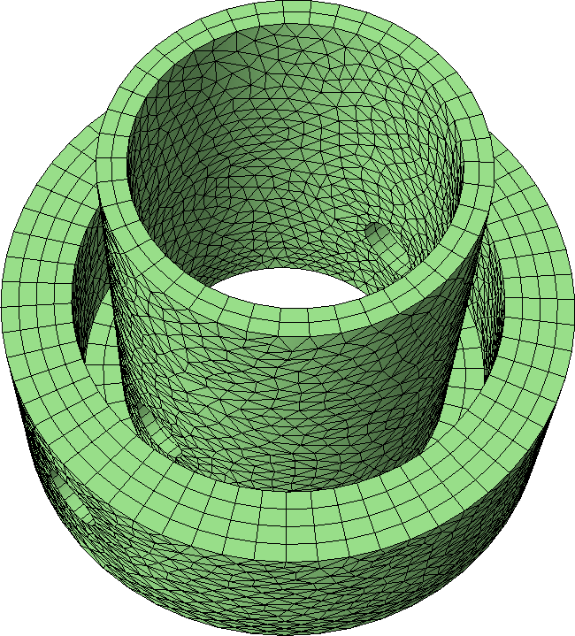
Radial Extrusions
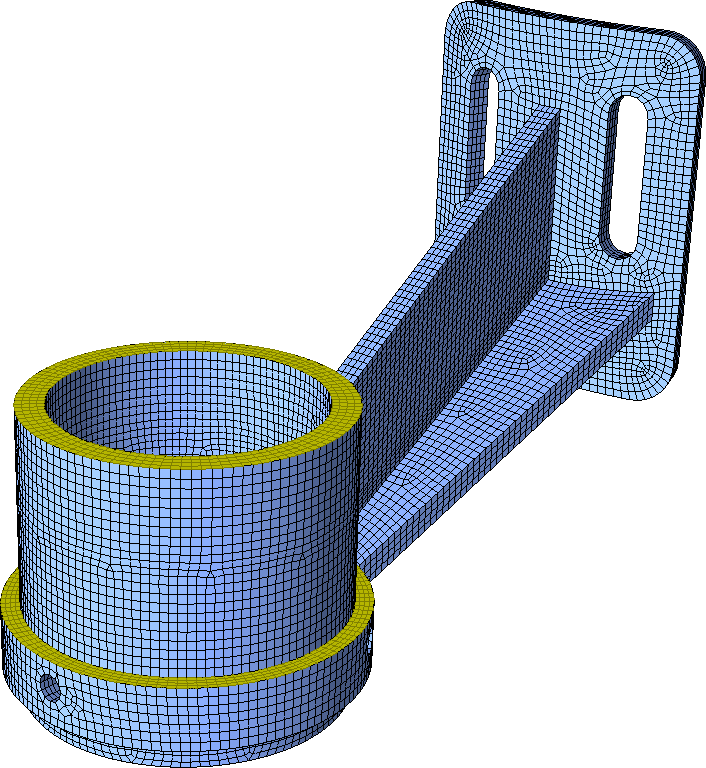
Extrusions can be specified in the radial direction, as shown with the highlighted yellow faces above and the concentric cylinders below.
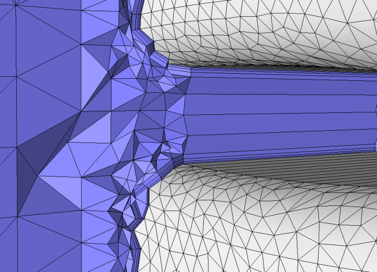
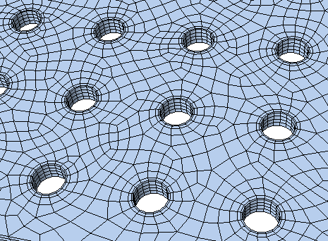
Boundary Layers with Extrusion
In the example below, boundary layers are specified on the holes to align the mesh with the holes and give precise control of the mesh size.
Graded Height Distributions
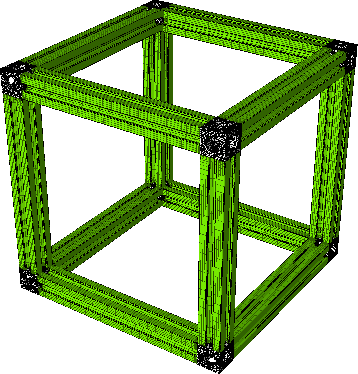
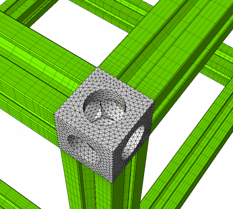
The structural bars are extruded with grading near the corners to more closely match the mesh size of the unstructured corner elements.